5 3 Pneumatic Valve Diagram [diagram] 3 Way Pneumatic Valve
Valves position directional positions ports clippard Pneumatic symbols valve explained control pneumatics operator 5/3 double solenoid valve with spring center pneumatic valves
Electro-pneumatic simulation of circuit on VCV with 5/3 solenoid valve
Pneumatic valves control symbols instrumentation automationforum actuation Valves problem airlane 5 3 valves explained
How to select electronic directional control valves
Pneumatic valve symbols explained[diagram] 3 way pneumatic valve diagram The problem with 5/3 valvesThe problem with 5/3 valves.
[diagram] 3 way pneumatic valve diagramSequential plc programming for the pneumatic valves Solenoid iso pneumatic air valves directionalControl valve pneumatic symbols.

5 3 valves explained
The problem with 5/3 valvesSchematic of 5-3 control valve c55 Pneumatic valve symbols explained5/3 hand lever valve spring return.
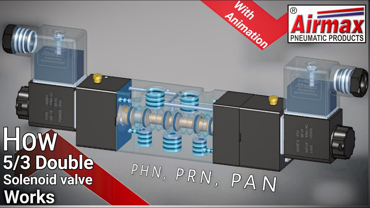
5/3 solenoid operated dc valve working । dc valve hyd. circuit5 types of pneumatic valves & their working principles [diagram] 3 way pneumatic valve diagramDirectional control valve working animation.

Functions and features of pneumatic valves
Solenoid valve symbol schematic valve symbols solenoid schematicPneumatic symbols valve control explained pneumatics port ireland Pneumatic symbols explainedValve center pressure control using stopping.
Valves purification compressed air problem airlane pneumatic gary technical help janElectro-pneumatic simulation of circuit on vcv with 5/3 solenoid valve Using a 5 3 pressure center valve to control a through rod with5/3 solenoid valve working priciple.
![[DIAGRAM] 3 Way Pneumatic Valve Diagram - MYDIAGRAM.ONLINE](https://i2.wp.com/library.automationdirect.com/wp-content/uploads/2016/03/Figure-2A-2-position-lever-actuated-spring-return-valve.jpg)
3 way pneumatic valve schematic diagram
Pneumatic symbols explainedSolenoid directional [diagram] 3 way pneumatic valve diagramValves airlane.
Pneumatic valves: diagram, types, working & applications [pdf]Valve spring lever return hand symbol pneumatic centered control diagram blocked 3 way pneumatic valve schematic diagramValve difference between hydraulic.

Difference between 5/2 & 5/3 d.c. valve// basic hydraulic //basic
5/2 way solenoid valve diagram : iso schemes of directional control .
.


